So, now we box it up. As you can see, the size of the PCB is pretty much spot on. Thanks digital calipers!
Everything was going swimmingly. I wired everything up, popped in the ICs, then plugged it in. The LED came on, a fantastic start! But there was no signal at all. So I went away and had a little cry, as you do when your board doesn’t work first time. After a strong cup of Yorkshire tea and some cake I came back to it slightly more determined than before. It was time to trouble shoot.
I’m always paranoid that I have a bad batch of ICs. It’s irrational, but I did once find that only three of ten PT2399s that I had actually worked. I can fairly confidently say that that’s just often the craic with PT2399s and not a general rule. I’ve not had any significant problems with any other ICs I’ve used. I’m just always worried that they’ve become damaged by static or something, but then I’m a worrier and like I say it’s a bit on the irrational side.
Remember there was no signal being passed at all, so, my first port of call was changing the TL072 and the TL074. If these were both working then you’d at least have the direct level coming through. Of course, after changing them nothing happened, still no signal. This shouldn’t be your first port of call.
When you have an issue like this ALWAYS assume that the mistake is yours, because the chances are that it IS your mistake. Don’t go blaming components until you’ve ruled out human error. Making mistakes and learning from them is all part of improving. Don’t fret about it.
Having said that, you should always check your PCB before you populate it with components. You should also double check your components with a mulitmeter before soldering. It is a little time consuming, but can save you hours if you’ve put a wrong value in somewhere.
Anyway, what I’d recommend is checking for cold solder joints first. I’m fairly confident in my soldering ability, but when I knock up a prototype, I don’t bother reflowing joints like I do with the pedals I sell, because I’m only interested in whether the circuit works.
So, I left the pedal plugged in, with the back off, turned upside down. Then I took a plectrum and tapped all the components. If everything is soldered correctly this shouldn’t make any noise at all. If you’ve got a dodgy joint, then tapping that component will cause the connection to cut in and out, or perhaps just create some kind of noise. If you find anything like that then, reflow the joint and try again. I didn’t. So obviously there were no cold joints.
Just to be safe I unscrewed everything and cleaned the back of the board with isopropyl alcohol as I normally would on the builds I sell. It’s possible that there’s a solder bridge or a rogue component leg snipping jumpering two sections that shouldn’t be connected. This tappy tapping was also fruitless. My soldering was solid, which is great, but not very helpful.
Next I checked the continuity of a couple of parts of the circuit with my DMM (digital multi-meter). I wasn’t getting anything from ‘in’ to pretty much anywhere on the circuit, which was my first clue.
Next, and this step should probably have come earlier, I checked the voltages on the pins of all the ICs and wrote them all down (in black).
I always keep the circuit set up on the breadboard until I’m 100% that everything is ok. So I went back to the breadboarded version (that I know works) measured all the voltages on all the pins, and wrote them next to the PCB values in red ink. Like this…

This was as far as I got, because it was obvious that something wasn’t right with that first op amp. Don’t forget to plug the power supply in before you do this. I’ve tried to debug a pedal that wasn’t plugged in before, it’s very time consuming.
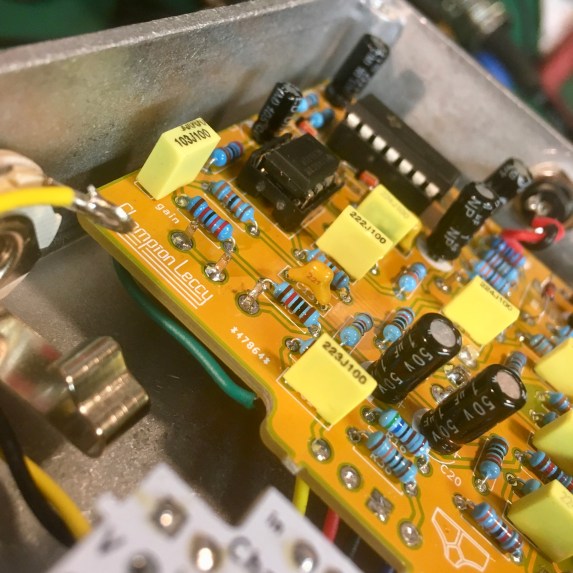
So it was time to check the connections to that TL072 on the PCB. Now my mistake was easy to spot. It was a simple and stupid mistake. The input cap and the biasing resistor were not connected to pin 3 of the TL072, in fact here was nothing connected to pin 3. This would explain why the voltage on pins 1,2 and 3 were much lower than they should have been.

It would also explain why the continuity checker wasn’t able to find anything from ‘in’. So how on earth did this really stupid mistake happen? If you’ve read the previous posts you’ll see that I removed the first JFET buffer. Here are my errors:
- I forgot to rename all the components for the sake of neatness. that’s why R4 is the first resistor in the circuit. Shoulda been neater. But this is unimportant, it just bugged me that I’d missed this.
- In KiCAD when you rename something in the PCB section of the software (I changed the name of U1 to TL072 in the PCB) then update the schematic and take the changes across it doesn’t update that component, it just pops a new one in there for you. I deleted that new one without thinking. So the remaining footprint for the TL072 was still looking for a component that wasn’t there. This was a little bit stupid of me.
- The big one. I obviously didn’t check the PCB in KiCAD before sending it off to dirty PCBs. I really thought I had, but obviously I hadn’t.
So, in future, when I’m sending a bunch of PCBs off for fabrication. I think I need a check list, and checking the tracks on every PCB should be ticked off before they get sent off. I remember checking a load of them (it was a big batch), but my fried brain obviously missed this one. Systems, systems we all need systems. It was a small and simple mistake that shouldn’t have happened.
So, did it work? What did you do? Well, I just jumpered a lead from pin 3 to the input cap. It’s the green one in the picture below.
And yeah, it works fine!
Here it is with a bass through it.
As you can see I gave the controls names too. All sausage or hand related of course.
gain – hair
direct level – bone
octave 1 – lard
mids – meat
bias – span
synth mod switch – gristle
Also, you can probably hear that the noise I was getting when it was on the breadboard is totally gone now too. There’s three possible reasons for that. 1 – The CD4013 is not right next to any other ICs. 2 – I don’t have any big ol’ jumper leads everywhere. All the tracks on the PCB are short. 3 – the metal enclosure forms a Faraday cage, which does nice things like cut out electrostatic noise.
In the next and last sausage fingers post for a while, I’ll talk about a few ideas I have for tinkering with in version 2.